The disadvantages of linear power supplies (LPS), such as lower efficiency, transformers used are heavier and large, more power is wasted in the form of heat, dissipation is more, etc, overcome by implication of SMPS. First, let us know about what is the full form of SMPS. SMPS is used as a controlled switch.
SMPS is based on the chopper principle. The output of the dc voltage is controlled by varying the duty cycle of chopper by PWM or in FM techniques. The circuit configuration used for SMPS can be classified into three broad categories, namely flyback, half-bridge, full-bridge.
Now let us talk about why go in for SMPS?
- An ac to dc rectifier operates at a supply frequency of 50 Hz. In order to obtain almost negligible ripple I the dc output voltage, physical size if the filter circuit is required large.
- This makes the dc power supply inefficient, bulky and weighty.
- On the other hand, SMPS also work like dc chopper.
Different kinds :
1. Full bridge converter :
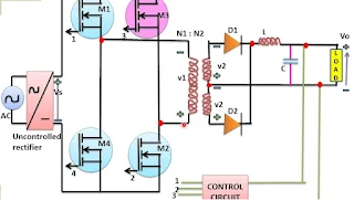
The circuit diagram for a full bridge SMPS is shown in the figure. It consists of an uncontrolled rectifier, four power MOSFETs are used, a transformer with mid tap secondary, two diodes and LC circuit, the function of the control circuit is to sense the output load voltage and to decide about the duty ratio of MOSFETs.
Full bridge converter operates with minimum voltage and current stress on the power MOSFET. It is therefore very popular for high power application above 750 W.
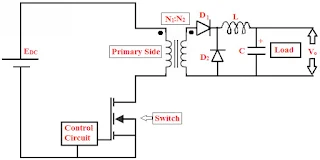
The circuit configuration for the flyback converter is shown in the figure. It consists of a power MOSFET M1, a transformer for isolation purpose, diode D, capacitor C, and load. An uncontrolled rectifier converts as to dc output which is to flyback SMPS as shown in the figure.
2. Half-bridge converter :
The circuit diagram of the half-bridge converter shown in the figure. It consists an uncontrolled rectifier, basically two capacitor C1 and C2, two power MOSFETs M1 and M2, and only one transformer with a mid tap on the secondary side, two diodes D1 and D2 and filter components L and C.
When M1 is totally off, the open-circuit voltage across the M1 terminal is Vs. When M2 is off, as before Voc = Vs. For, half-bridge converters is, therefore, preferred over push-pull converters.
3. Flyback SMPS :
Output power is very less(<100 W) when we are using flyback converter types SMPS and frequently used in low power application.
Advantages of SMPS :
- The efficiency is high as compared to LPS, more than 80 to 90%
- The device is used in SMPS is compact and very small in size
- The manufacturing cost is reduced
- Provide isolation between multiple outputs
- Low power wastage
- Less heat generation
- Lower weight
- Providing the required number of voltage
- Reduced the harmonic feedback into the supply mains
- Wide ac input voltage
- Greater circuit complexity
- The expert design is required
- The noise to present due to high-frequency switching
- It produces electromagnetic interference


