Showing posts with label Power electronics applications. Show all posts

UPS application

UPS full form is used in any field that requires an uninterruptible high-quality power supply. This article gives information about the UPS application to a better understanding of the UPS system.
  • Outdoor uses/military uses 
  • Multiple redundancy
  • Hospital
  • Data center
  • Telecommunication
  • Static power converter
  • Diesel ICE / hydrogen at an energy source
  • From couple of second up to couple of minute
  • Electrochemical battery are the main choice as energy storage
  • Alternative energy storage 
There are just some the industries that can benefits from UPS system :
  • Data and call centers devices
  • Universities
  • Telecommunication and cable companies
  • Electronics manufactures
  • Bank
  • Hospital and medical centers
  • TV station
  • Utility companies
  • Production based manufactures

Application of SMPS

SMPS meaning can be used in a variety of electronics equipment, including computer and other sensitive equipment.
  • Security system
  • Personal computer
  • Mobile phone charger
  • Machine tool industry
  • Railway system
  • Battery charger
  • Used in mobile
  • Used in vehicles
  • Used in lighting

SMPS meaning

Before knowing about the SMPS meaning one question you should be clear about is What is Full form of SMPS ?

SMPS is an electronics circuit and it can convert power using switching devices that are turned on and off at the high frequencies. 

SMPS can be used in a variety of electronics equipment, including computer and other sensitive equipment.

Types of SMPS :
  • DC to DC converter
  • Forward converter 
  • Fly-back converter
  • Self-oscillating fly-back converter

Uninterruptible power supplies

Before we learn about UPS system first let we check out what is full form of UPS. There are several applications of UPS where even a temporary power failure can cause a great deal of public inconvenience leading to large economic losses. UPS can be used in electrical equipment where unexpected power disruption could cause injuries, serious business, or data losses, and also some many more advantages of the UPS system. Earlier UPS systems were based on an arrangement shown in the figure. 

Working of rotating type UPS system :
  • This scheme is usually called rotating types UPS. This arrangement consists of DC motor driven alternator, the shaft of which is also coupled to a diesel engine. 
  • The UPS system needed is taken from the alternator output terminals. When the main supply fails, the diesel engine is run to take over the load. 
  • The battery bank is able to maintain the alternator speed through the dc motor and the flywheel, thus giving a no break supply to the critical load.
  • Static UPS system is two types, short break UPS and no break UPS. 
Short  break UPS :
  • In a situation where short interruption in supply can be tolerated, the short break UPS showed in the figure. In this system, the main ac supply is rectified to dc.
  • This dc output from the rectifier charges the batteries and is also converted to ac by an inverter. After passing through the filter, AC can be delivered to load in case normally off contacts are closed.
 No break UPS  :
  • When no break UPS supply is required, the static UPS system shown in the figure. In this supply is rectified and the delivered power to maintain the required charge on the batteries. 
When users no break UPS system has the following advantages :
  • The inverter can be used to condition the supply delivered to load
  • Load gets protected from transients in the main ac supply
  • The inverter output frequency can be maintained at the desired value In case of inverter failure is detected, the load is switched on the main ac supply directly by turning on the normally off static switch and opening the normally on a static switch.
The standby batteries in the UPS system are either nickel-cadmium or lead-acid types. NC battery has the following advantages :
  • Their electrolyte is non-corrosive. 
  • Their electrolyte does not emit an explosive gas when charging
  • NC batteries cannot be damaged by overcharging or discharging, these have therefore longer life
  • Cost of  NC  batteries is like, however, two or three times that of lead acid batteries.

Static switch definition

A switch having no moving part called as a static switch. Power semiconductor devices which can be turned on and off within a few microseconds can be used as fast acting static switches.

Static switches can be also used for latching, current and voltage detection, a time delay circuit, transducers etc.

A static switch is two types :
  1. AC switches
  2. DC switches 
If we are using input is ac then ac SS are used while we are using input is DC, DC SS are used. Switching speed for AC switches is governed by the supply frequency and turn off time of thyristor (SCR). 

For DC static switches, the switches speed depends on the commutation circuitry and turn off time of fast thyristor. AC switches may be single phase or three phases. 

Static switches do not change or control the power delivered to load as it is done in a single phase voltage controller In a static switch, the semiconductor switches are turned on at zero crossing of the load current, whereas it is not so single-phase voltage controller.

Static switches are now replacing mechanical and electromechanical switches because of several advantages listed below.
  • A static switch has no moving parts, It maintenance is therefore very low
  • A static switch has a long operational life
  • A static switch has no bouncing at the time of turning on
  • On time of a static switch is of the order of 3 microseconds, it has therefore very high switching speed
  • Inbuilt AC overvoltage protection
  • High-performance AC line quality monitoring

Advantages of static switches

Static switches are now replacing mechanical and electromechanical switches  both because of several advantages are listed below :
  • A static switch has no moving parts, therefore, maintenance cost  is very low
  • A static switch has a long operational life
  • A static switch has no bouncing at the time of when is turning on
  • On time of a static switch is of the order microseconds, it has therefore very high switching speed
  • Inbuilt AC overvoltage protection
  • High-performance AC line quality monitoring

Advantages and disadvantages of uninterruptible power supplies

The term UPS full form Uninterruptible Power Supplies typically used to protect as data centers, telecommunication, computers, and also have some other electrical equipment where unexpected power disruption could cause injuries, serious business, or data losses. This article gives information about the advantages and disadvantages of a UPS device to know more about the UPS device.

Advantages of Uninterruptible power supplies :
  • Emergency power supply
  • Maintain battery life
  • Provide surge protection
  • Protect some uncertain data loss
  • Use gives a huge power back in the industries
  • Reliable power source
  • Trusted power solution provider
  • Uncertain data loss can be prevented
  • Protect the voltage-sensitive device from bad electricity
Disadvantages of Uninterruptible power supplies :
  • Maintain cost is difficult
  • The startup cost is too much high
  • Commercial uses require a large number of batteries
There are just some the industries that can benefit from UPS system :
  • Data and call centers devices
  • Universities
  • Telecommunication and cable companies
  • Electronics manufactures
  • Bank
  • Hospital and medical centers
  • TV station
  • Utility companies
  • Production-based manufactures

Static circuit breaker

Definition of static circuit breaker :

The static circuit breaker is basically semiconductor-based circuit. This circuit breaker is capable of providing a fast and also a reliable interruption current. 

The static circuit breaker is of two types :
  1. Static AC circuit breaker 
  2. Static DC circuit breaker
Here this article gives information about two circuit breaker to know more details about circuit breaker.

Static AC circuit breaker :
  • A simple arrangement of static ac circuit breaker shown in the figure. The circuit can switch on and switch off by using two thyristors SCR 1 and SCR 2.
  • When thyristor SCR 1 is turn on a positive cycle alternative supply when the switch is on condition.
  • When SCR 1 is off, the current becomes automatically zero.
  • When SCR 2 turn on the negative cycle of alternative supply.
  • SCR 1 receives the gate pulse through the diode D2 and  SCR 1 receives the gate pulse through the diode D1.
 

Static DC circuit breaker :
  • A simple arrangement of static dc circuit breaker shown in the figure given below. Force commutation is essential for turning off a thyristor device.
  • When SCR1 turn on, load voltage becomes equal to supply voltage and capacitor get charge through the circuit source voltage Vs, resistor R, capacitor C and SCR 1.
  • When breaking the circuit, SCR 2 is turned on.
  • SCR 2 turn on and  SCR 1 turn off due to reverse voltage across it.
  • The capacitor again charge +Vs to -Vs through the circuit Vs, load C and SCR 2.
  • When capacitor C is totally charged to -Vs, a current through load will be zero and the same time current through R will less than the holding current of SCR 2.
  • At that time SCR 2 will get turn off naturally, from this the value R can be determined.

High voltage DC transmission

It is well known that electric power generated in power plants is transmitted to the load centre on three phase ac transmission lines. However, for bulk power transmission over long distance, High voltage DC transmission line are preferred. First let we talk about full form of HVDC.

The additional cost of converting and inverting equipment makes HVDC transmission uneconomical for low power supply over short distance. However for large power transmission over long distance, HVDC turn out be economical. As a result, HVDC links are being used worldwide at power levels of several gigawatts with the use of thyristor valve.

How does HVDC system work ?

As we know that when AC power is generated which can be converted into DC by using the rectifier. so in end of the line there are two terminals inverter and rectifier. rectifier convert AC to DC while the inverter convert DC to AC.

The power transmitted remains same at the receiving end of the line. In substation system having more then two converter stations and one transmission line is called as a two terminal DC system. DC is transmitted over long distance because  it decreases the losses and improve the overall efficiency. If more than two converter and interconnecting DC terminal lines called as multi-terminal DC substation.
HVDC transmission possesses the following advantages over AC transmission system

Advantages of high voltage DC transmission :
  • Fault clearance in HVDC is faster, therefore DC transmission system possesses improved transient stability
  • Size of conductor in DC transmission can be reduced as there is no skin effect
  • Cost is less as compare to the AC transmission
  • HVDC tower are less costly 
  • No requirement of reactive power
  • No system stability problem
  • HVDC require less phase to phase and ground to ground clearance
  • Require less number of conductor for same power transfer
  • Improve line loading capacity
  • HVDC is preferred as it requires no charging current 
  • Power loss is reduced  with DC just because of fewer numbers of lines are required for power transmission
  • HVDC is more flexible system

Disadvantages of high voltage DC transmission :
  • Expenses inverters with limited overload capacity
  • HVDC is less relaible
  • IN HVDC very accurate and lossless power flows through DC link
  • The disadvantages of HVDC are in conversion, switching, control, mainatance
  • Lower availability than AC system
  • HVDC  is very complicted 
  • circuit breaker are used in HVDC for circuit breaking, and Inverter and rectifier terminals will generate harmonics which can be reduced by using active filters, which are also very expensive
  • HVDC does not have transformers for changing the voltage levels
  • Heat loss occurs in converters substation

HVDC advantages and disadvantages

HVDC links are being used worldwide at power levels of several gigawatts with the use of thyristor valve. So here this article gives information about the advantages and disadvantages of HVDC to know more details about it. 

Advantages of high voltage DC transmission :

  • Fault clearance in HVDC is faster, therefore the DC transmission system possesses improved transient stability
  • Size of the conductor in DC transmission can be reduced as there is no skin effect
  • Cost is less as compared to the AC transmission
  • HVDC tower is less costly 
  • No requirement of reactive power
  • No system stability problem
  • HVDC require less phase to phase and ground to ground clearance
  • Require less number of conductor for same power transfer
  • Improve line loading capacity
  • To ac system at different frequencies can be interconnected through HVDC transmission lines
  • HVDC is preferred as it requires no charging current 
  • Power loss is reduced  with DC just because of fewer numbers of lines are required for power transmission
  • HVDC is a more flexible system

Disadvantages of high voltage DC transmission :

  • Expenses inverters with limited overload capacity
  • HVDC is less reliable
  • IN HVDC very accurate and lossless power flows through DC link
  • The disadvantages of HVDC are in conversion, switching, control, maintenance
  • Lower availability than the AC system
  • HVDC  is very complicated 
  • The circuit breaker is used in HVDC for circuit breaking, and Inverter and rectifier terminals will generate harmonics which can be reduced by using active filters, which are also very expensive
  • HVDC does not have transformers for changing the voltage levels
  • Heat loss occurs in converters substation

Advantages and disadvantages of SMPS

The disadvantages of linear power supplies (LPS), such as lower efficiency, transformers used are heavier and large, more power is wasted in the form of heat, dissipation is more etc. Overcome by implication of SMPS. So now let us talk about the advantages and disadvantages of SMPS to know more details about SMPS. first, let us check it out full form of SMPS

Advantages of SMPS :
  • The efficiency is high as compare to LPS, more than 80 to 90%
  • The device is used in SMPS is compact and very small in size
  • The manufacturing cost is reduced
  • Provide isolation between multiple output
  • Low power wastage
  • Less heat generation
  • High power density
  • Flexible technology
  • Lower weight
  • Providing the required number of voltage
  • Strong anti-interference
  • Reduced the harmonic feedback into the supply mains
  • Wide ac input voltage
Disadvantages of SMPS :
  • Greater circuit complexity
  • Expert design are required
  • High frequency electrical noise
  • It can be used step down regulator 
  • The noise to present due to high-frequency switching
  • It produces electromagnetic interference
  • Harmonic distortion
  • Only one output voltage
  • Expensive compared to LPS
The main advantages of SMPS over conventional linear power supply are as under :
  • SMPS is less sensitive to input voltage variations
  • For the same power rating, SMPS is of smaller size, lighter in weight, and possesses higher efficiency because of its high-frequency operation.
The disadvantages of SMPS are as under :
  • SMPS has higher output ripple and its regulation in worse
  • SMPS is a source of both electromagnetic and radio interference due to the high-frequency switching
  • Control of radio frequency noise requires the use of filters on both input and output of SMPS

Explore more information:

What is smps in computer

The disadvantages of linear power supplies (LPS), such as lower efficiency, transformers used are heavier and large, more power is wasted in the form of heat, dissipation is more, etc, overcome by implication of SMPS. First, let us know about what is the full form of SMPS. SMPS is used as a controlled switch.

SMPS is based on the chopper principle. The output of the dc voltage is controlled by varying the duty cycle of chopper by PWM or in FM techniques. The circuit configuration used for SMPS can be classified into three broad categories, namely flyback, half-bridge, full-bridge.


Now let us talk about why go in for SMPS?
  • An ac to dc rectifier operates at a supply frequency of 50 Hz. In order to obtain almost negligible ripple I the dc output voltage, physical size if the filter circuit is required large.
  • This makes the dc power supply inefficient, bulky and weighty.
  • On the other hand, SMPS also work like dc chopper. 
Different kinds :

1. Full bridge converter :

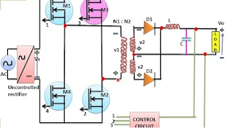
The circuit diagram for a full bridge SMPS is shown in the figure. It consists of an uncontrolled rectifier, four power MOSFETs are used, a transformer with mid tap secondary, two diodes and LC circuit, the function of the control circuit is to sense the output load voltage and to decide about the duty ratio of MOSFETs.

Full bridge converter operates with minimum voltage and current stress on the power MOSFET. It is therefore very popular for high power application above 750 W.


Full bridge converter

2. Half-bridge converter :

The circuit diagram of the half-bridge converter shown in the figure. It consists an uncontrolled rectifier, basically two capacitor C1 and C2, two power MOSFETs M1 and M2, and only one transformer with a mid tap on the secondary side, two diodes D1 and D2 and filter components L and C.

When M1 is totally off, the open-circuit voltage across the M1 terminal is Vs. When M2 is off, as before Voc = Vs. For, half-bridge converters is, therefore, preferred over push-pull converters. 

Half-bridge converter
3. Flyback SMPS :

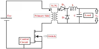
The circuit configuration for the flyback converter is shown in the figure. It consists of a power MOSFET M1, a transformer for isolation purpose, diode D, capacitor C, and load. An uncontrolled rectifier converts as to dc output which is to flyback SMPS as shown in the figure.

Output power is very less(<100 W) when we are using flyback converter types SMPS and frequently used in low power application.

Flyback SMPS


Advantages  of  SMPS :
  • The efficiency is high as compared to LPS, more than 80 to 90%
  • The device is used in SMPS is compact and very small in size
  • The manufacturing cost is reduced
  • Provide isolation between multiple outputs
  • Low power wastage
  • Less heat generation
  • Lower weight
  • Providing the required number of voltage
  • Reduced the harmonic feedback into the supply mains
  • Wide ac input voltage
Disadvantages of SMPS :
  • Greater circuit complexity
  • The expert design is required
  • The noise to present due to high-frequency switching
  • It produces electromagnetic interference