PCB advantages and disadvantages

The PCB stands for the printed circuit board. This board is a very vital part of modern electronic equipment. Printed circuit board consists of a very large number of passive as well as active components required. The components are connected from side to side with traces on the board. It is absolutely to develop very large circuits on small printed circuit boards with the availability of very small-sized electronic components. Let us have a deep insight into the advantages and disadvantages of the printed circuit board to know more about it. 

Advantages of PCB :

  • PCBs has a low cost, mass production can be achieved at a lower cost.
  • It is Re-workable.
  • Widely available.
  • Excellent shelf life
  • This board gives low electronics noise.
  • Compact size and saving of wire.
  • Inspection time is reduced because PCBs eliminates the probability of error.
  • This board takes less time in assembling a circuit as compared to the conventional method.
  • In this design, there is no chance of loose connections or short circuit.
  • If in case of any damage, it is very easy to check and replace the particular failure components.
  • Printed circuit board design to offer uniformity of electrical characteristics from assembly to assembly.
  • The location of the electronic part is fixed and it is easy to simplify components identification and maintenance of equipment.
  • Component wiring and assembly both can be mechanized in a circuit board manufacturing facility.
  • All of the above factors bring reliability in the performance of the circuit.

Disadvantages of PCB :

  • Uneven PCB surfaces finish.
  • Not good for fine-pitch.
  • It contains lead.
  • Thermal shock.
  • Solder bridging.
  • Not easy to repair once damaged.
  • It can be used for a specific circuit.
  • We cannot be updated, once printed.
  • Plugged or reduced.
  • Redesigning is required for one type of circuit operation.
  • The etching process generates chemicals which are a harmful effect on the environment.
Explore more information:

Soldering advantages and disadvantages

Soldering makes quick and neat connections to electronics equipment and plumbing. Soldering may require more practice, skills and some perfect knowledge for doing it. In this article, let us have a deep insight into the merits and demerits of soldering to better understand this topic.

Advantages of soldering:

  • It is simple, low cost, flexible, economical and user-friendly.
  • Base metal does not melt, so the low-temperature heat source can be used. 
  • Any metals, non-metals can be joined by this process.
  • This can be operated at a low temperature.
  • Less time required to join.
  • The life of the solder will be more.
  • Soldered joints can be dismantled.
  • This can be easily operated.
  • Low process temperature.
  • Low amount of power is required to heat the soldering iron.
  • Thin wall part may be joined.
  • Easily automated process.
  • Dissimilar material may be joined.
  • This operation required low power.
  • The soldering can be done at low temperature, and control very easy.
  • No thermal distortion and residual stresses in the joint parts. 
  • The microstructure can no be affected by heat. 

Disadvantages of soldering:

  • This is not useful when joint works under high temperature. 
  • Strength of the joint is less.
  • Soldering process can not join heavy sections.
  • It is suitable for only small parts.
  • It is not useful at long length weldings.
  • Heavy metals cannot be welded by this operation.
  • There is a chance to toxic components at fluxes.
  • Careful removal of flux residuals is required in order to prevent corrosion. 
  • The large section can not be joined.
  • Skilled labour is required for soldering.

Advantages and disadvantages of breadboard

We all know about basic knowledge about breadboard, it is cone in the form of the rectangular boxes perforated with holes for mounting electrical projects. Holes must be punched on the test cards are commonly called nodes. They are used to insert wires and some electronics part through them to complete electrical circuits, so easy to mount your electrical project on a breadboard. 

A breadboard is readily available and also it is inexpensive to use on your PCB design. In the market, there is a lot of different type of breadboard available such as the Velleman SD 35n solderless breadboard, self-adhesive mini Tie point.  Let us have a deep insight into the advantages and disadvantages of Breadboard to know more about it. 

Advantages of Breadboard :

  • It has easy to quick to check for easy and complex circuits both and it has easily verified circuits at the initial stage, so it can save time.
  • Quick to check component around.
  • It is easy to adjust.
  • It is flexible.
  • No drilling holes.
  • No soldering required.
  • It can be debugged easily.
  • A solderless connection makes it reusable.
  • Cheap and connections can be changed. 

Disadvantages of breadboard :

  • It is unreliable.
  • Difficult to replicate.
  • It is temporary.
  • It is heavier.
  • A breadboard is noisier than properly laid-out circuit boards, sometimes far too noisy.
  • It is difficult to troubleshoot due to human error and some poor connections problem.
  • Not good for high current applications.
  • Not meant for withstand high voltage anything above 48 V. 
  • It works very poorly for high-speed design.
  • Difficult to modify complex SMD component for prototyping.
  • It almost always, take up more physical space than the final circuit board design.
  • High parasitic inductance and resistance and capacitance between adjacent rows. 
Explore more information:

Conclusions :

The breadboard has easy to quick to check for easy and complex circuits both and it has easily verified circuits at the initial stage. So in all over the world, we all know that every electronics or in the electrical project must be designed on a breadboard. But, as the designing complexity of the project circuit increases and consume more time with the increases in the complexity of the project. So there are used some advanced tools and board such as PCBs, and so on for designing complexities and save time.

So here this page has the right place to design and implement your own electronics project using a breadboard with proper knowledge. So any queries regarding designing and implementing problem on breadboard please comments in the comments section below. 

Yagi UDA antenna advantages and disadvantages

The yagi UDA antenna is a particularly popular form of the antenna where directivity and gain must be required. The yagi UDA antenna offers many advantages over the other types of antennas in a lot of applications. However, it is necessary to weigh both advantages and disadvantages to ensure that the correct antenna type is chosen for any particular use.

Advantages of yagi UDA antenna:

  • It is simple to build.
  • It is a compact size and also it is must in lightweight.
  • It offers wide bandwidth due to the use of folded dipole.
  • It is lower cost because easy of handling and maintenance.  
  • It offers a unidirectional radiation pattern which is reasonably good.
  • It offers substantial increases in directivity and gains compared to the considered simple dipole antenna.
  • It can be easily mounted with standard mechanical fixings on vertical poles or other poles.
  • High gain is achieved about to 7 dB. 
  • Less amount of power is wasted.
  • Frequency coverage is broad. 

Disadvantages of yagi UDA antenna:

  • It is sensitive to frequency.
  • It does not offer very high gain limited around 20 dB. 
  • The design is obstructive in nature.
  • Bandwidth is reduced if a number of director element is used in the array.
  • Need a large number of elements to be used.
  • It is prone to noise. 
  • It is also prone to atmospheric effect. 

Conclusion :

The Yagi antenna is a very practical form of RF antenna design suitable for applications requiring gain and direction. Although the cost is higher than the basic antennas, the Yagi often offers the most cost-effective gain and directional option.

LM358 pinout | Introduction | Configuration | Features | Packages | Advantages | Application

As we know that there are available in various forms of 555 timers, single logic gates, microcontrollers, microprocessors, voltage regulators and op-amps like different ICs IC  LM741, LM7805, LM35, LM324 IC, LM337LM338LM339 ICLM340LM1117 and many more ICs are available. Here we have to learn or introduce IC LM358 because it has low power and easy-to-use dual-channel op-amp IC. This IC is designed especially to operate from a single power supply over a wide range of voltages. It is a good, standard operational amplifier and the most important point for this IC is suitable for your needs. LM358 IC is available in a small size as a chip. This IC is most commonly used in the device due to its cost-efficiency. Let us have a deep insight into the introduction, pinout, configuration, features, packages, advantages, and applications of LM358.

Introduction to LM358 :


LM358 consists of two independent compensated operational amplifiers with high gain frequency. LM 358 IC is available in the cheap sized package so this must be used in real-life applications including DC gain block, conventional OP-AMP circuits design, active filters, and transducer amplifier,  This post also gives some information about these ICs like Pinout of LM358, features, Applications, advantages, Pin configuration of LM358, Also give some real-life applications of LM358. So you have to learn some different ideas related to your project you are in the right place to study.

Pinout LM358 :

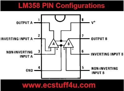
  • LM 358 has eight (8) pins in total having different individual functions associated with each of them.
  • Pin-1 and pin-8 are the output of the comparator.
  • Pin-2 and pin-6 are inverting inputs.
  • Pin-3 and pin-5 are non-inverting inputs.
  • Pin-4 is the GND terminal.
  • Pin-8 is VCC+.
LM358 IC pinout

LM358 pin configurations :

  • Here I have to represent with a complete pin diagram along with full animations.
  • A properly labelled pin diagram of any device results in better standing of the user, so the users can easily understand pin configurations.
  • The complete pinout diagram along with animation, a real image of LM358 and symbolic representation is shown in the figure below.
LM358 pin configurations

Features of LM358 IC :

  • It consists of 2 OP-AMP internally.
  • The output voltage swing is high.
  • The large DC voltage gain is around 100 dB.
  • Wider bandwidth in 1 MHz(Temperature compensated).
  • The supply current drain is very low.
  • Wider power supply, in the single power supply, is 3V to 32 V while the dual power supply is +or-1.5 V to +or- 16 V.
  • 2mV low input offset voltage.
  • Common mode input voltage range comprises ground.
  • The differential input voltage range is similar to the power supply voltage.
  • Internally frequency compensated for unity gain.
  • Short circuit protected outputs.
  • Soldering pin temperatures at 260 C.
  • The available packages are TO-99, SOIC, DSBGA, and CDIP.

LM358 packages :


The available package is TO-CAN, SOT-23(5), DSBGA, PDIP. all of these packages along with their dimensions and part numbers are given below:

PACKAGES:

PDIP(8) - 9.81 𝝬  6.35 and unit - mm
DSBGA(8) - 1.31  𝝬 1.31 and unit - mm
TO-CAN(8) - 9.08  𝝬 9.09 and unit - mm
SOIC(8) - 4.90  𝝬 3.91 and unit - mm

Advantages of the LM358 IC :

  • Two operational amplifiers are compensated internally.
  • Permits direct sensing close to GND and VOUT.
  • Well suited with all methods of logic.
  • Power drains are appropriate for the operation of the battery.
  • Two internally compensated for OP-AMP.
  • Eliminates the need for dual supplies.

LM358 applications :


LM358 has a wide range of real-life applications, we have represented the major applications of LM358 listed below:
  • It must be used in the DC gain block.
  • It can be used for signal conditioning.
  • It is used for active filters.
  • Current loop transmitter for 4 to 20mA.
  • It can be also used in transducer amplifiers in real-life applications.
  • This IC also be used in operational circuits.
  • It must be used in real-life applications like shock alarm circuits and dark sensor circuits.

Simple Schock alarm circuit using LM358 :

  • The shock alarm circuit using LM358 is very easy to design and it has many applications from home automobiles.
  • The main application of this circuit is as an anti-theft alarm in automobiles. In this circuit, a piezoelectric sensor is used as a shock sensor that has to be mounted on the door which you have to guard. 
  • Here shown in figure LM358 is connected in the inverting Schmitt trigger. The port R1 sets the threshold voltage of the circuit. R1 is used as the feedback resistor.
  • When the piezoelectric sensor has not activated the output from the piezoelectric sensor will be low and so will the output of the IC, So at a time output of the sensor is high and activates as a Schmitt trigger. Then it gives the buzzer sound. 
  • The buzzer remains beeping for some time even if the vibration is detached. This is because when inverting input has little effect when the LM358 IC is triggered and the state can't be easily inverted. So fix the sensor firmly to the surface, wherever you place it and it is always good to place the sensor near to the doorknob. 
  • So here this figure has to use the 3-volt battery as a power supply and regulate the R2 register to obtain the necessary sensitivity.
Schock alarm circuit using LM358


Conclusions :


Here this post gives the all about information IC LM 358 like pinout, pin configurations, applications, advantages, features, and also real-life applications. We hope you all understand this topic. Furthermore, for queries regarding your project please give your feedback by commenting in the comment sections.

Advantages and disadvantages of geothermal energy

Geothermal comes from the Greek word Geo which means earth and Thermo which mean heat. So, as we know that geothermal energy means energy or power extracted from beneath the earth. Geothermal energy is a type of thermal energy which is generated and stored on the earth. To understand geothermal of energy, imagine having a fireplace nearby, one which will never go out. Let us have a deep insight into the pros and cons of Geothermal energy to know more about it. 

Advantages of geothermal energy:

  • It is a renewable source of energy.
  • It is non-polluting and environment-friendly.
  • There is no wastage or generation of by-products.
  • Geothermal energy can be used directly.
  • It is reliable and stable.
  • Highly sustainable.
  • Low emissions.
  • Very less noise pollution,
  • Independent on whether unlike solar energy.
  • Massive potential.
  • Increase in employment.
  • High efficiency of energy conversion.
  • The maintenance cost of geothermal power plants is very less.
  • Geothermal power plants don't occupy too much space and thus it helps in protecting the natural environment.
  • Unlike solar energy, It is not dependent on for weather conditions.

Disadvantages of geothermal energy:

  • Only a few sites have the potential of geothermal energy.
  • Total generation potential of the eruption of a volcano.
  • These plants may affect the stability of the land.
  • It is based on location-specific.
  • Most of the sites, where the geothermal energy is produced, are far from markets or some cities, where it needs to be consumed.
  • Drilling and exploitation of it too much expensive.
  • Environmental concern due to the release of greenhouse gases during extraction.
  • There is always a danger of eruption of a volcano.
  • The installation cost of the steam power plant is very high.
  • There is no guarantee that the amount of energy which is produced will justify the capital expenditure and too many operations costs.
  • It may release some harmful, poisonous gases that can escape through the holes drilled during construction.
  • Pumps are required for extracting it may require external power, which may possibly come burning fossil fuels.

LM35 pinout | Introduction | Features | Working | Advantage | Application

As we know that there are available in various forms of 555 timers, single logic gates, microcontroller, microprocessor, voltage regulator and op-amps like different ICs IC  LM741, LM339 ICLM358, LM338LM337, LM7805, and many more ICs are available. LM35 is a precision of IC is a temperature sensor with its output is proportional to the temperature, in the form of Celcius. This IC is most commonly used in an industrial and commercial building where high accuracy of temperature measuring is needed. Here this gives the information about basic introduction about LM35, specification of LM35, Pinout of LM35 and application about LM35, advantages, and lastly working of IM35. Let us have a deep insight into the brief understanding of IM35 pinout. 

Introduction to LM35 :

  • LM35 is a commonly used in temperature sensor, It shows values in the form of output voltage instead of degree celsius. 
  • It does not require any external calibration circuitry.
  • LM35 shows high voltage values than thermocouple and may not need that the output voltage is amplified.
  • The sensitivity of LM35 is 10mV/degree celsius. As the temperature increases, the output voltage also increases.
  • One of the most important characteristics is that it draws just 60uA from its supply and acquires a low heating capacity.
  • The output voltage is always is proportional to the Celsius temperature. The scale factor is .01 V/ C
  • The LM35 temperature sensor is available in many different packages like TO-92 plastic package form, 8 lead surface mount SO-8 small outline package. 
  • LM35 gives temperature output is more precise than thermistor output.

LM35 Pinout Diagram :


LM35 has three pinouts which are given below with figure:

PIN 1: Vcc, it is used as input at this pin we supply +5V input voltage.
PIN 2: At this pin, we get output voltage.
PIN 3: This pin is used for ground.


LM35 pinout diagram


 LM35 Features :

  • Low-cost temperature sensor.
  • Minimum and maximum voltages are 35V and -2V respectively, Typically 5V.
  • Drain current is less than 60uA.
  • Small and hence suitable for remote applications.
  • 0.5 C accuracy guarantee able
  • Can measure temperature ranging from -55 ̊ C to 150 ̊ C.
  • Available in TO-92, TO-220, TO-CAN and SOIC package.
  • The output voltage is directly proportional to temperature there will be a rise of 10mV for every 1 ̊ C rise in temperature.
  • Suitable for remote applications.

LM35 Working :

  • LM35 is a precision of temperature sensor with its output is proportional to the temperature. The sensor is circuitry is sealed and therefore it does not subject to oxidation and other processes. 
  • LM35 temperature can be measured more accurately than with a thermistor. 
  • The output voltage range of this sensor is from -55 to 150 C.  It also has low self-heating power.
  • Operating voltage is 4 to 30 Volts.
  • This sensor is used with an operational amplifier which amplifies a voltage at a certain level.  
  • In operational amplifier there are three terminals, first two are inverting and non-inverting input and the third one is used for the output. 
  • So by using the IC LM35 with an operational amplifier, we can get amplification of output voltages of LM35.
LM35 Working Diagram


LM35 Advantages:

  • Low self-heating.
  • This IC and circuit are not too much complected.
  • It does not require signal conditioning.
  • It requires only 4 to 30 V voltage.

LM35 Applications :

  • It is used for measuring the temperature of a particular environment.
  • Monitoring battery temperature and also provides battery protection from overheating.
  • Providing thermal shutdown for a circuit or a component used in a specific project.
  • It can be used for measuring temperature for HVAC transmission.

Conclusions :

Here this post gives the all about information of IC LM 35 like pinout, applications, advantages, and features. We hope you all understand this topic. Furthermore, query regarding your project please give your feedback by commenting in the comment sections.

Advantages and disadvantages of squirrel cage induction motor

Squirrel cage induction motor is widely used in industries this is the reason this kind of three-phase induction motor which uses as squirrel cage motor is known as the squirrel cage induction motor. This motor is very robust in construction and also very cheap. Squirrel cage induction motor consists of part like stator, rotor. Stator which is a stationary part and rotor which is a rotating part. Let us have a deep insight into the pros and cons of squirrel cage induction motor to know more about it. 

Advantages of squirrel cage induction motor :

  • Squirrel cage induction motor is cheaper in cost compared to slip ring induction motor.
  • This motor required less maintenance as compared to the slip ring motor.
  • Rugged construction.
  • Generate less heat.
  • Squirrel cage motor is better cooled compared to slip ring induction motor.
  • Squirrel cage motors operate at nearly constant, high overload capacity, and operates at better power factor.
  • Squirrel cage motor is explosion-proof due to the absence of brushes slip ring and brushes which eliminates the risk of sparking.
  • Squirrel cage motor operates at a nearly constant speed, high overload capacity, and operates at a better power factor.
  • Squirrel cage induction motor requires less conductor material than slip ring motor, hence copper losses in squirrel cage motor are fewer results in higher efficiency compared to slip ring induction motor. 

Disadvantages of squirrel cage induction motor :

  • Poor starting torque.
  • High starting current.
  • Speed control is not possible in a squirrel cage induction motor., in short, no speed regulation.
  • Sensitive to change in supply voltage.
  • More sensitive to the supply voltage regulation fluctuations.
  • Total energy loss during stating of squirrel cage motor is more compared to the slip ring motor. 

Center tapped full wave rectifier vs bridge rectifier

The main key difference between a center tap full-wave rectifier and bridge rectifier is that one uses a center-tapped transformer while another does not require a center-tapped transformer. Both these types are used full-wave rectifier but their method of converting AC input into DC is different by employing a different number of diodes. Let us have to deep inside the information about the difference between center tap full wave rectifier and bridge rectifier to better understand this topic.

Center tap full wave rectifier vs bridge rectifier:

  • Center tap full wave rectifier need for center-tapped transformer while Bridge rectifier does not need the required center-tapped transformer.
  • Both have an efficiency of 81.2%.
  • Both have a 0.48 ripple factor.
  • The peak inverse voltage rating of the diode in a bridge rectifier is half than that needed in a center-tapped full-wave rectifier. The voltage coming across each diode is twice the maximum across the half of the secondary winding is the center-tapped full-wave rectifier.
  • In center tap, full-wave rectifier peak inverse voltage of diode in center-tapped full-wave rectifier is twice the secondary terminal voltage, while in bridge rectifier the PIV of the diode is equal to the transformer secondary voltage. Thus this type of rectifier can be used for high voltage applications.
  • In the center tap, full-wave rectifier there is two number of the diode are required while four diodes are required for the bridge rectifier.
  • In center-tapped full-wave rectifier transformer utilization factor must be equal to 0.672 while the Bridge rectifier transformer utilization factor must be equal to 0.810.
  • The transformer size i.e kVA rating required for center-tapped rectifier is more, while the bridge rectifier transformer size requirement is less.
  • The transformer utilization factor for a center-tapped full-wave rectifier is 0.693 while 0.812 in the case of a bridge rectifier. 
  • The ripple factor for both of them is the same as 0.48. The form factor for both of them also same as 1.11. The peak factor for both of them is the same as √2.
Explore more information:

Difference Between Potentiometer and Rheostat

The construction of both the rheostat and potentiometer is almost the same but the main difference is the way we used it for operation. It potentiometers, we use all the three terminals for performing the operation whereas in rheostats we use only two terminals for performing the operation. Let us have a deep insight into a comparison and difference between them to know more about it. 

Definition of Rheostat:

A rheostat is a basically resistor, which is used to control the flow of electric current by manually increasing or decreasing the resistance. Rheostat can be defined as a "Rheos" and "-Statis" which means a stream controlling device or current controlling device. Rheostat having two terminals.

Definition of Potentiometer:

Potentiometer which is also known as a "Pot", which has a resistor with three terminals and sliding contact with an adjustable voltage divider.

Difference between potentiometer and Rheostat :

  • The potentiometer is a component having three terminals, Rheostat has two terminals.
  • The potentiometer is a sliding contact with an adjustable voltage while the rheostat is a variable resistor.
  • A potentiometer can be used as a rheostat, but as a potentiometer, a rheostat can not be used.
  • The potentiometer is often used to vary voltage and rheostats are used to vary current.
  • The potentiometer is used as a measuring instrument or component as in electronics whereas rheostats are used to vary the resistance of a circuit.
  • A potentiometer is made of resistive elements such as graphite, resistance wire, cermet, and carbon particles while a rheostat is made of various materials such as fluids, metal ribbons, and carbon disks.
  • A potentiometer has low power and used for audio devices, television control, and as a transducer while a rheostat is used for high power and appliances like fans, mixers, and the motors and the motors of large industrial machines.

Rheostats and potentiometers are still used today but nowadays they are being replaced by the TRIAC also known as a silicon control rectifier because of that mechanical parts corrode and break after some time which can cause them to malfunction.

Explore more information:
  1. Difference between resistor and capacitor
  2. Difference between resistor and resistance 
  3. Difference between resistor and reactance
  4. Difference between resistor and inductor
  5. Difference Between Cell and Battery
  6. Capacitor vs supercapacitor

Infrared sensor advantages and disadvantages

The infrared sensor is a device which uses infrared waves to sense the characteristics of the surroundings. It is used to measure heat emitted by an object or human being. It can be also used for data communication for monitoring and control applications. Here this post gives information about the pros and cons of an infrared sensor to better understand this topic.

Advantages of infrared transmission:

  • They do not require contact with the object for detection.
  • It provides secure communication.
  • They are no leakage of data due to beam directionality IR radiation.
  • They are not affected by corrosion or oxidation.
  • It provides good stability over time.
  • It delivers high repeatability.
  • It has a response time faster than a thermocouple.
  • No corrosion or oxidation can be affected by the accuracy of the infrared sensor
  • They have very strong noise immunity.
  • Their low power requirement makes them suitable for most electronic devices such as laptops, telephones, and PDAs.
  • Infrared motion sensor detects motion in daytime and nighttime reliably.
  • This sensor does not require any contact with the product to be sensed. The infrared devices are more appropriate for targets which are closer than 10 mm.
  • They are capable of detecting motion in the presence or absence of light almost with the same reliability.
  • The battery-used infrared devices last for a long duration due to lower power consumption.
  • The infrared device can measure the distance to the soft object which may not easily be detected by ultrasound.
  • They are physically small in size and are more affordable.
  • It provides secured communication due to line of sight or points-to-point modes of communication.

Disadvantages of infrared sensor:

  • The required line of sight.
  • Limited range, support a shorter range.
  • Get blocked by common objects.
  • The transmission data rate is low.
  • Can be affected by environmental conditions such as rain, fog, dust, pollution, sunlight, smoke, etc.
  • Infrared waves at high power can damage the eyes.
  • In monitor and control applications, it can control only one device at a time. Moreover, it is difficult to control things that are not in LOS. It requires a line of sight between transmitter and receiver to communicate.

Difference between RTD and thermistor

As we know that the RTD and thermistor both are temperature measuring device. The major difference between the thermistor and RTD is that the RTD is made of metal while the thermistor is made that semiconductor material. Let us have a deep insight into the comparison between them and understand more about RTD and thermistor. 

Difference between RTD and thermistor :

  • The RTD is made of the metal a positive temperature coefficient whereas the thermistor is made of the semiconductor materials.
  • The RTD is less sensitive as compared to the thermistor.
  • The cost of the thermistor is much higher than RTD.
  • The size of the RTD is much larger as compared to the thermistor material.
  • The resistivity of the RTD is less as compared to the thermistor.
  • The thermistor gives a quick response to the small changes, whereas the response time of the RTD is low.
  • The characteristics are used for measuring the small range of the temperature up to 130 °C whereas the RTD measures the temperature up to 660 °C.
  • The hysteresis effect in the thermistor is much high as compared to the RTD device.
  • The characteristics graph between resistance and temperature of the RTD is linear whereas that of the thermistor it is nonlinear.
  • The RTD used in the industries for measuring the high temperature whereas the thermistor we used in home appliances for measuring the small temperature.
  • The accuracy of the RTD is low as compared to the thermistor.
  • The RTD is made of metals having a positive temperature coefficient whereas the thermistor is made of the semiconductor materials.
  • Thermistor has a much faster response time compared to RTDs.
  • RTDs have a greater temperature range compared to thermistors devices.

Conclusion:

Thermistor and RTD both are the temperature sensing device. A thermistor is used for measuring the temperature of small devices while RTDs is used for measuring the high temperature.

Advantages and disadvantages of full wave rectifier

As we know a full-wave rectifier, can convert an alternating voltage (AC) voltage into a pulsating direct current (DC) voltage using both half cycles of the applied AC voltage. When we have to use a full-wave rectifier uses two diodes of one conduct during a one-half cycle with other conduct during the other half cycle of the applied AC voltage.

If you want to learn some different you are in the right place to read so keep reading for a few minutes for the right information regarding full-wave rectifiers. Let us have a deep insight into the pros and cons of a full-wave rectifier

Advantages of full-wave rectifier:

  • The ripple frequency is two times the input frequency.
  • Efficiency is higher.
  • The large DC power output.
  • Ripple factor is less.
  • The ripple voltage is low and the higher frequency in the case full-wave rectifier so a simple filtering circuit is required.
  • Higher output voltage.
  • Higher transformer utilization factor.
  • Utilizes both halves of the AC waveform.
  • Easier to provide smoothing as a result of using the ripple frequency.

Disadvantages of full-wave rectifier:

  • More complected than half-wave rectifier.
  • It requires more diodes, two for the centre tap rectifier and four for the bridge rectifier.
  • The PIV rating of the diode is higher.
  • Higher PIV diodes are larger in size and too much costlier.
  • The cost of the centre tap transformer is high.
  • The twice-frequency hum on an audio circuit may be more audible.
  • This rectifier is difficult to locate the centre tap on the secondary winding.
  • The DC output is small as using each of diode utilized only one-half of the transformer's secondary voltages.
  • When a small voltage is required to be rectified, the full-wave rectifier circuit is unsuitable.
Explore more information:

Advantages and disadvantages of bridge rectifier

With the availabilities of low cost, highly reliable and small-sized silicon didoes bridge rectifier is becoming more and more popular in comparison of center tap and half-wave rectifier. So if you want to learn some different you are the right place for reading so keep reading for a few minutes for the right information regarding full-wave rectifier. Let us have a deep insight into the pros and cons of a full-wave rectifier and also many more advantages over the center tap and other is to be half-wave a rectifier as listed below.

Advantages of bridge rectifier:

  • The need for the center-tapped transformer is eliminated.
  • It can be used in application floating output terminals, no output terminal is grounded
  • Transformer utilization factor, in case of the bridge rectifier, is higher than that of a center tap rectifier.
  • If stepping up or stepping down of the AC voltage is not needed, and it does not even require any transformer.
  • The PIV is one half that of center tap rectifier. Hence bridge rectifier is highly suited for high voltage applications.
  • The transformer is less costly as it is required to provide only half the voltage of an equivalent center-tapped transformer used in a full-wave rectifier.
  • Transformer utilization factor, in case of the bridge rectifier, is higher than that of a center tap rectifier.
  • For high voltage applications, bridge rectifier preferred, because it has high peak inverse voltage.

Advantages of bridge rectifier over a center tap transformer:

  • The size of the transformer used in a bridge rectifier is smaller than that in the center tap transformer.
  • The bridge rectifier utilizes the entire transformer during the entire cycle of a time period of the voltage/ current waveform, center tap uses only for 50% of the transformer.
  • A bridge rectifier may use a transformer or may not use a transformer. It depends on the necessity of stepping up or down of voltages.
  • The number of diodes used in a bridge rectifier is 4, while the number of diodes used in the center tap rectifier is only 2. 
  • The peak inverse voltage rating PIV of the didoes in the bridge rectifier is 1/2 of the PIV rating in case of center tap rectifier. That means that one needs high quality and costlier diodes for center tap rectifier. 

Disadvantages of bridge rectifier:

  • In this type, two extra diodes are used. So it requires four semiconducting didoes.
  • Two diodes in series conduct at a time on alternate half-cycles. This creates a problem when low DC voltages are required. This leads to poor voltage regulation.
  • Internal resistance voltage drop is twice than that of the center tap circuit.
  • If stepping up or stepping down of voltage is not needed, we may even do without a transformer.